
This guide covers the variables that actually govern screw conveyor performance: the five primary design parameters, how to work through a capacity calculation, how incline changes your entire design approach, and which mistakes introduce the most serious operational risks. These principles apply across chemical processing, food and grain handling, pharmaceutical manufacturing, and mineral processing — the industries where screw conveyors do the most critical work.
Key Takeaways
- Five interdependent variables drive screw conveyor performance: diameter, pitch, speed, trough loading ratio, and bulk density.
- Trough loading ratios of 15%, 30%, and 45% map to non-free-flowing, average, and free-flowing materials.
- Inclination reduces capacity significantly; design compensations include reduced pitch, tubular housing, and larger diameter.
- Material properties at the conveyor inlet — not upstream — are the correct design basis.
- Motor sizing for inclined conveyors must account for upset restart conditions, not steady-state flow alone.
Key Design Variables That Determine Screw Conveyor Performance
Screw conveyor performance depends on the interaction of five primary variables: screw diameter, screw pitch, rotational speed, trough loading ratio, and material bulk density. Adjust any one of them and the others shift in response.
Screw Diameter
Diameter is the foundational sizing decision. Larger diameters allow slower speeds to achieve the same volumetric throughput, which directly reduces wear and the risk of material degradation.
According to KWS Engineering guidance, standard screw diameters range from 4 inches to 36 inches, with ANSI/CEMA 350 confirming that 30-inch and 36-inch screws were formally added to the dimensional standard. Diameter selection must also account for particle size — secondary engineering guidance indicates maximum lump size should not exceed 25% of screw diameter for mixed lumps and fines, or 15% for all-lump material.
Screw Pitch
Once diameter is set, pitch controls how aggressively the screw moves material forward.
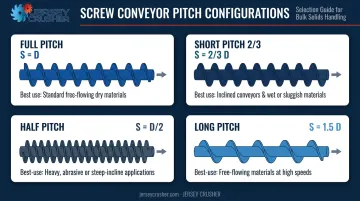
Standard pitch configurations and their appropriate applications:
| Pitch Type | Ratio | Best For |
|---|---|---|
| Full pitch | S = D | Horizontal runs, free-flowing materials |
| Short (2/3) pitch | S = 2/3 D | Inclined and vertical applications |
| Half pitch | S = D/2 | Steeper inclines, sluggish materials |
| Long pitch | S = 1.5 D | Faster throughput at lower RPM |
Trough Loading Ratio
The trough loading ratio defines what fraction of the screw cross-section carries material. Using industry engineering guidance:
- 15% — non-free-flowing or abrasive materials
- 30% — average flowability materials
- 45% — free-flowing materials with low abrasiveness
Overloading the trough is one of the most common causes of blockages and motor overload. Internal hanger bearings reduce the effective loading area — consult the manufacturer before assigning a loading percentage.
Rotational Speed
Speed must stay within recommended maximums for a given diameter. As diameter increases, maximum RPM drops — running a large-diameter screw too fast accelerates wear and risks material degradation.
Reference points from KWS engineering data at 15% trough loading:
| Screw Diameter | Approximate Max RPM |
|---|---|
| 4 inches | ~69 RPM |
| 36 inches | ~30 RPM |
These are secondary engineering values. ANSI/CEMA 350 contains the authoritative maximum speed tables and should be the final reference before finalizing any speed specification.
Step-by-Step Screw Conveyor Capacity Calculation
The general engineering formula for estimating screw conveyor capacity:
Q = (π/4) × D² × S × N × α × ρ × C
Where:
- Q = output (kg/h)
- D = screw diameter
- S = pitch
- N = rotational speed (RPM)
- α = trough loading ratio
- ρ = bulk density
- C = inclination correction factor
Use this as a concept-level sizing tool. Detailed design should go through a qualified manufacturer.
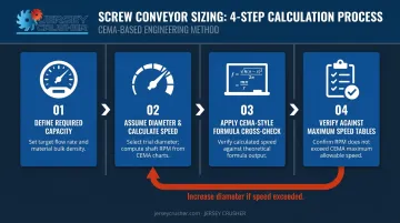
Step 1: Define Required Capacity
Start with the required mass or volumetric flow rate at the discharge point. For example: a plant conveying sugar requires 3,500 kg/h. The design capacity should include a service factor margin above this minimum — a conveyor sized exactly to minimum requirement leaves no room for density variations or process upsets.
Step 2: Assume Diameter and Calculate Speed
The process is iterative:
- Assume a starting diameter
- Select appropriate pitch for the application
- Assign trough loading ratio based on material flowability
- Solve for required RPM
If calculated RPM exceeds the recommended maximum for that diameter, step up to the next standard diameter and recalculate. Never increase speed to compensate — this creates centrifugal and wear problems.
Step 3: Apply the CEMA-Style Formula as a Cross-Check
The CEMA-derived alternative formula accounts for the pipe shaft diameter and gives capacity in ft³/h at 1 RPM:
C = 0.7854 × (Ds² − Dp²) × P × K × 60 / 1728
Where Ds = screw diameter, Dp = pipe shaft diameter, P = pitch, K = trough loading as a decimal, 60 = minutes per hour, and 1728 = cubic inches per cubic foot.
Multiply the result by operating RPM to get volumetric capacity. This formula is useful for validating the general formula result or checking an existing conveyor against new capacity requirements.
Step 4: Verify Against Maximum Speed Tables
After calculating required RPM, check it against the manufacturer's or CEMA's maximum speed table for the selected diameter and trough loading. If calculated speed exceeds the maximum: increase diameter, recalculate, and verify again. Do not override speed limits.
Inclined Screw Conveyor Design: Efficiency Losses and Compensations
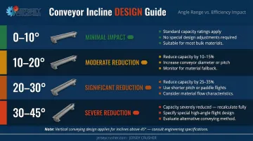
Inclination changes screw conveyor behavior because gravity causes material to fall back over the flights rather than advance. This reduces effective capacity — and the steeper the angle, the more pronounced the effect.
CEMA 350 confirms Chapter 7 covers inclined and vertical screw conveyors, and secondary engineering sources define four incline bands with distinct design responses:
| Incline Range | Efficiency Impact | Design Response |
|---|---|---|
| 0–10° | Minimal | Standard U-trough and full pitch acceptable; speed or diameter increase can compensate |
| 10–20° | 10–40% reduction | Switch to 2/3 pitch; U-trough still workable; increase speed or diameter; additional HP needed |
| 20–30° | 10–70% reduction | Tubular housing required; use 1/2 or 2/3 pitch; larger diameter recommended |
| 30–45° | 30–90% reduction | Tubular housing with reduced pitch and larger diameter essential; significant HP increase required |
Above 45°, the unit must be designed as a vertical screw conveyor under separate CEMA guidelines.
Upset Conditions and Motor Sizing
The upset condition is a risk specific to inclined installations. When material feed is interrupted — due to an outage, blockage, or process stop — material inside the conveyor slips back and redistributes. When the conveyor restarts, it faces near-100% trough loading rather than steady-state loading.
The motor must be sized for this worst case. CEMA 351-2007 documents that starting torque for screw feeders can reach 2.5 times demand running torque — that figure applies specifically to screw feeders, but it illustrates the scale of torque demand at startup under full load. Confirm the appropriate uprating factor with your manufacturer before finalizing motor selection. Housing choice directly affects how much material redistributes during an outage, which is where the next design variable comes in.
Tubular Housing vs. U-Trough
U-troughs leave an open area above the screw where material falls back at higher angles. Tubular housings fully enclose the screw and dramatically reduce that fallback — which is why they're essential above 20° incline.
The tradeoff: tubular housings limit access for cleaning and inspection. In food, pharmaceutical, and chemical applications where cleanability matters, this requires deliberate attention during the design phase. Jersey Crusher's screw conveyors use enclosed tube construction to support both inclined installations and contamination-sensitive environments — their engineers can work through configuration requirements based on your specific angle, material, and cleanability constraints.
Material Properties and Design Compatibility
CEMA classifies bulk materials by particle size, flowability, abrasiveness, and corrosivity. Each characteristic directly governs a design decision:
- Flowability → trough loading ratio (15/30/45%)
- Abrasiveness → flight material, thickness, and speed conservatism
- Corrosivity / food-safety requirements → construction material and enclosure class
- Lump size → minimum screw diameter
Construction material selection determines both conveyor life and product compliance:
- Carbon steel — cost-effective for non-corrosive, non-food industrial applications
- 304 stainless steel — covers most food and mildly corrosive chemical environments
- 316 stainless steel — required for pharmaceutical applications, aggressive chemicals, and higher-tier food processing
- Abrasion-resistant alloys — extend flight life when handling minerals, fertilizers, or other abrasive bulk solids
Jersey Crusher manufactures screw conveyors in all four of these configurations, with carbon steel units finished in blue enamel for added durability. The right material choice depends on what the conveyor carries — pharmaceutical powder, raw sugar, and mineral feedstock each impose different requirements.
Material properties change after upstream processing. A product discharged from a lump breaker carries different lump size characteristics than the same material sitting in a storage bin; a material exiting a dryer has different moisture content and flowability than it did going in. Screw conveyor design should always be based on the material's condition as it enters the conveyor — not its original state.

Common Design Mistakes That Introduce Operational Risks
Undersizing Diameter or Oversizing Speed
Running a screw too fast for its diameter causes material to cling to the outer flight rather than advance — centrifugal effects effectively stop forward conveyance. Overloaded troughs create torque spikes that shear shafts or burn out motors. Both scenarios produce unplanned downtime and accelerate component wear.
The fix is disciplined application of maximum speed tables during design. If the required throughput demands a speed above the maximum for the selected diameter, move to the next diameter up. A larger diameter costs more upfront; unplanned downtime costs far more.
Ignoring Inclination Correction in Capacity Planning
Engineers who carry horizontal capacity numbers through to inclined installations routinely end up with equipment that cannot meet throughput requirements under actual operating conditions. The efficiency losses at inclination are substantial — and they compound at startup when the upset condition brings the conveyor to near-full trough loading.
Two rules apply without exception:
- Known incline angle: Apply the correction factor, select the appropriate pitch, and size the motor for restart loads before finalizing the design.
- Assumed negligible incline: Verify that assumption with the manufacturer — small angles still carry meaningful efficiency penalties.
Combustible Dust Risk
Conveyors handling combustible bulk materials — grain dusts, sugar powders, pharmaceutical powders, certain chemical powders — carry explosion risk if designed without appropriate precautions. Both ATEX 2014/34/EU (for EU installations) and NFPA 654 (for US facilities) establish requirements for equipment in potentially explosive atmospheres. NFPA 652 provides the fundamental combustible dust framework applicable across US facilities.
The specific design requirements — including speed limits, enclosure ratings, and ignition control features — depend on the material's dust explosion class and facility classification. Work directly with the equipment manufacturer and a qualified safety engineer to determine the applicable standard and design to it. Vendor tip-speed guidance is not a regulatory limit — confirm the actual requirement for your specific facility classification before finalizing any design.
Frequently Asked Questions
What is the recommended trough loading ratio for a screw conveyor?
Loading ratios depend on material flowability:
- 15% for non-free-flowing or abrasive materials
- 30% for average flowability materials
- 45% for free-flowing materials
Use the lower end of each range when internal hanger bearings are present, as they reduce effective cross-sectional area.
How does incline angle affect screw conveyor capacity?
Capacity drops with inclination because gravity causes material to fall back over the flights instead of advancing. Efficiency losses begin at 10° and increase significantly through 45°. Trough type, screw pitch, and motor sizing must all be adjusted as inclination increases.
When should I use a tubular housing instead of a U-trough?
Tubular housings are recommended for inclines above approximately 20°, applications requiring dust containment, or where material fallback in an open trough would unacceptably reduce capacity. The tradeoff is reduced access for cleaning and inspection.
What screw pitch is best for inclined conveying applications?
Reduced pitches (1/2 or 2/3) outperform full-pitch screws on inclines because the flight face sits more perpendicular to the material load, reducing fallback and improving conveying efficiency. Full pitch is appropriate for horizontal runs with free-flowing materials.
How do I size a screw conveyor motor for upset conditions?
Motors for inclined conveyors must be sized to restart under near-100% trough loading after a flow interruption, not just for steady-state operation. Apply an uprating factor above the normal horsepower calculation. Consult your manufacturer for the appropriate factor based on your incline angle and material.
What materials are screw conveyors typically constructed from?
The four primary construction materials are:
- Carbon steel — general industrial use
- 304 stainless steel — food and mildly corrosive chemical applications
- 316 stainless steel — pharmaceutical and aggressive chemical environments
- Abrasion-resistant alloys — highly abrasive bulk solids
Material selection should align with your bulk material properties and any applicable regulatory requirements.