Introduction
Poor trough alignment is one of the leading causes of premature screw conveyor failure—yet it's routinely overlooked during installation. Misaligned troughs cause fatigue failures, accelerated wear, and unplanned downtime that can shut down production for days across chemical processing, food manufacturing, and bulk material handling operations.
A misalignment as small as 1/8 inch creates cyclical bending forces that fatigue screw sections at hanger bearing locations. These failures are frequently misdiagnosed as component defects rather than installation errors—masking the real problem.
The difference between a conveyor that runs for years and one that fails every few months comes down to measurement discipline: how carefully horizontal and vertical planes are checked, how accurately readings are documented, and whether the right adjustment method is applied at each support location.
This guide covers:
- Tools and preparation required for field alignment
- A step-by-step string-line process validated by CEMA standards
- Key variables that affect alignment outcomes
- Common mistakes operators make—and troubleshooting steps for recurring failures after completed alignment work
Key Takeaways
- Trough misalignment creates cyclical bending forces that cause fatigue failures at hanger bearings
- Check alignment in both horizontal and vertical planes across the full conveyor length
- Maximum allowable misalignment is 1/8 inch per direction under CEMA Standard No. 352
- Use a string line at trough centerline with measurements every 5 feet before making adjustments
- Replace hanger bearings with more than 1/8-inch wear — they reintroduce misalignment regardless of trough adjustments
How to Align Screw Conveyor Troughs: Step-by-Step
Step 1: Inspect the Trough Structure and Support Conditions
Before touching any fasteners, inspect every trough section, flange connection, and support stand for visible damage, deformation, or uneven settling. A bent trough section cannot be shimmed into alignment—it must be repaired or replaced first, or you'll waste hours attempting to correct an unfixable mechanical problem.
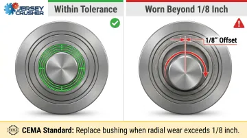
Check hanger bearings and coupling shafts for wear exceeding 1/8 inch. CEMA standards explicitly mandate replacement of hanger bearings when radial wear reaches this threshold, because worn components introduce angular offset that persists after alignment and accelerates re-failure. Document any components requiring replacement before proceeding with alignment work.
Lock out and tag out the drive unit. Verify the conveyor is fully de-energized. All trough flanges must be accessible, and fasteners must be loose enough to allow controlled section movement during the adjustment process.
Step 2: Set Up the String Line Reference
Secure a taut string line (or piano wire) to one end of the screw conveyor at the trough end plate, positioned at the screw centerline or at a fixed, measurable distance from the top flange. This establishes the straight reference datum for all horizontal and vertical measurements.
Pull the string line to the opposite end and anchor it tightly. Any sag introduces false readings—use a string tensioner and confirm the line clears all intermediate trough sections. Run two separate passes:
- Horizontal deviation check: String positioned at the side of the trough at screw centerline height
- Vertical deviation check: String positioned at the bottom of the trough flange
Label measurements from each pass clearly to avoid confusion during correction.
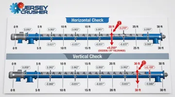
Step 3: Measure and Document Misalignment Along the Full Length
Starting from the anchored end, measure the distance from the string line to the reference edge of the trough at every 5-foot interval along the full conveyor length. Industry experts recommend checking alignment deviations every 3 to 5 feet to catch intermediate sections that may be bowed or offset even when endpoints appear visually straight. Record all values in a log before touching any fasteners or supports.
Repeat the process in the vertical direction, measuring from the string line to the bottom flange at the same intervals. Calculate the difference between consecutive measurements to identify offset sections. Any single-section jump greater than 1/8 inch requires correction before proceeding.
Step 4: Adjust Trough Sections to Achieve Proper Alignment
Loosen the fasteners at trough flange connections of sections identified as out of tolerance. Do not fully remove fasteners—loosening is sufficient to allow controlled movement while keeping the section captive.
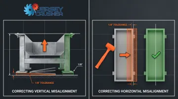
Correcting vertical misalignment:
- Add or remove shims at trough support/stand locations beneath out-of-tolerance sections
- Make small, incremental shim changes and re-check measurements after each adjustment
- Never assume a shim height is correct—verify with measurements before tightening
Correcting horizontal misalignment:
- Push or pull the trough section laterally to the measured target position
- Use a rubber mallet or carefully applied force on the trough flange if the section resists movement
- Never strike the trough body directly
Once both planes are within tolerance, retighten all trough flange fasteners evenly to specified torque values.
Step 5: Verify Screw Clearance and Perform a Test Run
With flanges secured, rotate the screw by hand if accessible, or jog the drive unit briefly, to confirm flights are not contacting trough walls at any point. Rubbing or uneven clearance signals residual misalignment or a damaged section missed during inspection—address it before proceeding.
Remove the string line, restore all guards and covers, and perform a no-load test run. Watch for:
- Abnormal vibration or noise at hanger bearing locations
- Visible lateral movement of the screw assembly
- Any binding or inconsistent rotation suggesting mechanical interference
If any of these appear, stop the conveyor and re-inspect the affected section before resuming operation.
Document the final measurement readings at all 5-foot intervals as a baseline record for future maintenance checks and re-alignment reference.
What You Need Before Starting Trough Alignment
Confirm all components are accessible and the system is properly locked out/tagged out before gathering tools. Alignment work on an energized conveyor is a serious safety hazard that can result in severe injury or death.
Equipment and Tools Required
The minimum toolkit includes:
- String line with tensioners (or piano wire)
- Measuring tape calibrated to 1/16-inch precision
- Spirit level or digital level
- Set of wrenches or impact driver for trough flange fasteners
- Rubber mallet
- Assorted metal shims in varying thicknesses
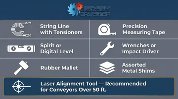
A laser alignment tool can replace the string line for longer conveyors and provides faster, more precise readings over spans exceeding 50 feet.
System and Component Readiness
All hanger bearings and coupling shafts must be inspected and confirmed within wear tolerance (under 1/8-inch wear) before alignment. Attempting to align a conveyor with worn bearings is counterproductive because the worn components immediately reintroduce offset under load. Conveyors manufactured to tight tolerances, like those from Jersey Crusher, tend to need these pre-alignment replacements less often because components hold their dimensions longer under service loads.
Operator Knowledge and Safety Readiness
The technician performing alignment should be familiar with the specific conveyor's installation drawings before starting. Key references to have on hand include:
- Designed support locations
- Trough flange bolt torque specifications
- Nominal screw-to-trough clearance
Consult the manufacturer's installation manual if any of these are not immediately available.
Key Parameters That Affect Screw Conveyor Trough Alignment
Technique matters, but four physical variables in the conveyor's design and operating environment determine how well alignment holds — and how fast it fails if left unchecked.
Conveyor Length and Number of Trough Sections
The longer the conveyor and the more trough sections it contains, the more cumulative misalignment can develop. Each section joint is a potential offset point, and small errors compound over distance.
CEMA recommends supporting trough assemblies every 10 to 12 feet to prevent cumulative deflection. Long conveyors (50+ feet) with multiple hanger bearings are the most common failure sites — misalignment-related fatigue risk scales directly with conveyor length and the number of intermediate support points.
Hanger Bearing Wear and Condition
Hanger bearings physically constrain the screw shaft position within the trough. A worn bushing lets the shaft deflect from centerline, creating a bending load on every revolution — no matter how well the troughs are aligned.
Wear beyond 1/8 inch in a hanger bearing bushing introduces a 1/8-inch misalignment at that location. CEMA maintenance standards require regular inspection and replacement when wear exceeds this threshold. Operating with worn bearings drives fatigue failures at coupling bolt holes and shaft ends.
Support Structure Stability and Foundation Settlement
Even a correctly aligned conveyor will drift if the support structure beneath it moves. Support stands anchored to concrete floors or structural steel that shifts, vibrates, or settles pull trough sections out of position over time.
Conveyors in environments with thermal cycling, high vibration from adjacent equipment, or non-rigid platforms need more frequent re-alignment checks. The mounting surface must be level and true, and trough assemblies must be securely anchored to prevent drift.
Trough Flange Flatness and Bolt Torque Consistency
Warped or corroded trough flanges prevent sections from mating flush, creating an angular offset at every joint. Uneven bolt torque compounds this — pulling one side of the flange tighter than the other reintroduces the same offset you just corrected.
Check and address flange condition during any re-alignment. Consistent, even torque at all fastener positions is required to lock in the adjusted position without shifting it back. One specific note: internal coupling bolts should be torqued to 75% of standard bolt torque values to prevent tensile failure.
Common Mistakes When Aligning Screw Conveyor Troughs
Most alignment failures trace back to the same handful of procedural errors. Recognizing them before you start saves significant rework time.
- Skipping pre-alignment inspection: Adjusting trough positions while leaving worn hanger bearings in place causes the conveyor to fail again at the same locations within weeks. Worn bearings allow shaft deflection regardless of trough positioning, so the cyclical bending forces never resolve.
- Checking only the endpoints: Measuring at the two ends while skipping 5-foot intermediate intervals misses bowed or offset trough sections that aren't visible from either end. These hidden stress concentrations cause failures in areas the operator assumed were fine.
- Adjusting multiple sections at once: Making large, simultaneous corrections across several sections makes it impossible to isolate which adjustment fixed which deviation — and often introduces new offsets in adjacent sections. Adjust one section, verify the measurement, document the result, then move to the next.
- Neglecting the vertical plane: Most operators focus on horizontal (side-to-side) deviation because it's more intuitive, but vertical misalignment produces the same cyclical bending forces and causes equal damage to screw sections and hanger bearings.

Troubleshooting Screw Conveyor Alignment Problems
Even after a careful alignment procedure, recurring issues can emerge during operation. The following covers the most common alignment-related symptoms, their likely causes, and corrective steps.
Repeated Screw Section Failures at Hanger Bearing Locations
Repeated failures at hanger bearing locations typically point to fatigue from cyclic bending stress — either trough sections were not brought within 1/8-inch tolerance, or worn bearings were left in place when alignment was locked in.
Steps to correct:
- Re-run the full string line measurement to confirm current alignment readings
- Replace any hanger bearing bushings showing wear greater than 1/8 inch
- Verify trough flange fasteners are properly torqued and have not loosened under vibration
Excessive Vibration or Noise During Operation
Contact noise and vibration usually mean screw flight contact with the trough wall — caused by misalignment, a bent screw section, or a loose flange connection allowing relative movement under load.
Check the following:
- Jog the conveyor and listen for where the noise localizes — contact sound pinpoints the section where clearance is lost
- Re-check alignment at that section and inspect the screw flight for deformation
- Retighten any loose trough flange bolts
Alignment Drifting Out of Tolerance Shortly After Correction
Drift that reappears after correction usually points to inadequately anchored support stands, foundation movement from vibration or thermal cycling, or undertorqued flange fasteners loosening during operation.
Steps to correct:
- Verify all support stand anchor bolts are fully tightened and base plates are flush with the mounting surface
- Apply thread-locking compound to trough flange fasteners in high-vibration environments
- Increase inspection frequency to catch drift early
If misalignment keeps recurring despite correct procedure and proper anchoring, the conveyor itself may have been manufactured to loose dimensional tolerances. Jersey Crusher's screw conveyors are engineered to tight tolerances for applications where alignment stability is critical.
Material Leaking or Building Up at Trough Joints
When fine material escapes or builds up at trough joints, the flanges are not mating flush — typically from misalignment, flange distortion, or debris preventing full contact.
Check the following:
- Inspect flange faces for warping, corrosion, or debris
- Confirm all flange gaskets (if used) are intact and seated correctly
- Re-align the affected section and retighten fasteners evenly to specified torque values
Frequently Asked Questions
How do you properly align a screw conveyor and prevent misalignment?
Proper alignment involves running a string line at trough centerline, measuring deviation in both horizontal and vertical planes at 5-foot intervals, and correcting each section with shims or lateral adjustment until all readings are within 1/8-inch tolerance. Regular inspection of hanger bearings and coupling shafts prevents wear from reintroducing misalignment.
What is the maximum angle for a screw conveyor?
Standard horizontal screw conveyors are designed for inclinations up to approximately 20–45 degrees depending on material characteristics and flight configuration. Above 45 degrees, units are classified as vertical conveyors, according to the KWS Screw Conveyor Engineering Guide. Inclined operation affects throughput efficiency and alignment requirements due to increased axial loading on bearings.
What is the direction of rotation for a screw conveyor?
The correct rotation direction depends on whether the screw is right-hand or left-hand flighted. A right-hand screw rotating clockwise (viewed from the drive end) moves material away from the drive. The direction must match the flight hand to achieve the intended material flow direction.
How often should screw conveyor trough alignment be checked?
Alignment should be verified during initial installation commissioning and after any maintenance involving trough section removal or repositioning. Schedule recurring checks every 6 to 12 months, adjusted based on operating hours, material abrasiveness, and vibration environment.
What causes screw conveyor troughs to go out of alignment?
The most common causes introduce cumulative offset that compounds over the conveyor's length:
- Foundation settlement or support stand movement
- Progressive wear in hanger bearing bushings
- Loose trough flange fasteners allowing section drift
- Thermal expansion in high-temperature applications
What tools are needed to align a screw conveyor trough?
Core tools for trough alignment include:
- String line with tensioners (or laser alignment system for longer runs)
- Precision measuring tape and spirit or digital level
- Assorted metal shims and a rubber mallet for lateral adjustment
- Wrenches for trough flange fasteners